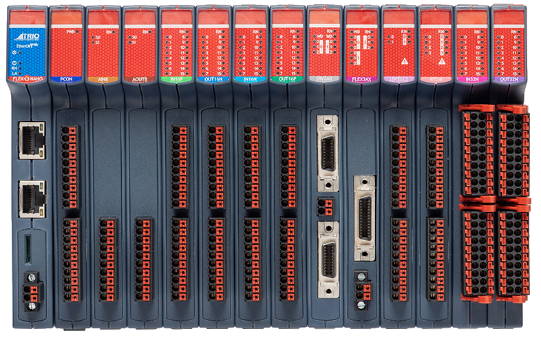
Overview
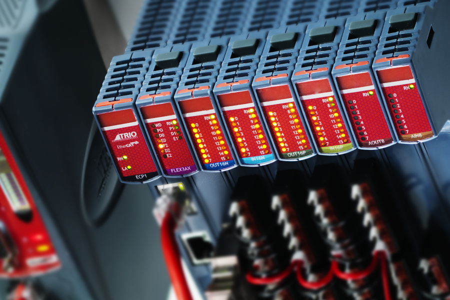
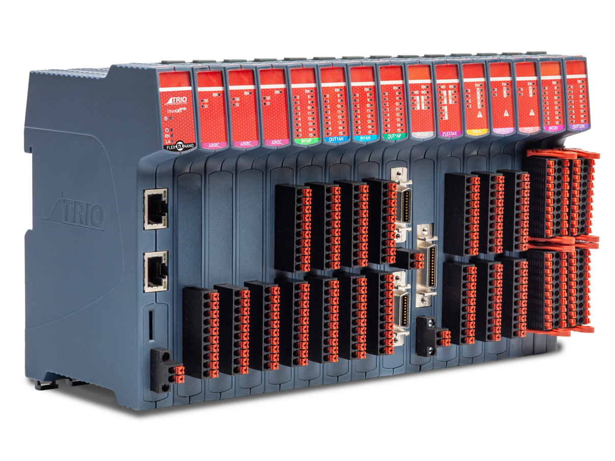
The EtherCAT Flexslice System is designed to let you do more!
It offers fast modular, scalable and flexible expansion for motion applications and can be used with Trio or 3rd Party Masters.
An advantage of the I/O slice approach compared to a traditional PLC for analogue and stepper integration is a saving on footprint and cost, combined with our motion-first specialisation.
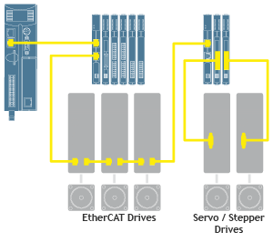
Flexslice EtherCAT I-O system offers all of this, but with focus on a motion-first solutions engineering. Flexslices include stepper + servo axes slices, as well as digital, analogue and sensor input slices, and combined with the powerful 64 axes Flex-6 Nano machine controller delivers a motion performance advantage.
Highlights
- Use with Trio or 3rd Party EtherCAT Masters
- High performance, flexible topology and simple configuration.
- Bus cycle time synchronised with Motion Coordinator Servo Period.
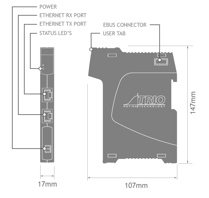
- Bus coupler module with 2 x RJ45 Ethernet ports for EtherCAT connection.
- EtherCAT protocol remains fully intact down to individual modules using the EBUS system.
- I/O functions tightly synchronised to motion using EtherCAT distributed clocks.
- Automatic mapping to the Motion Coordinator I/O system.
- DIN rail mounted.
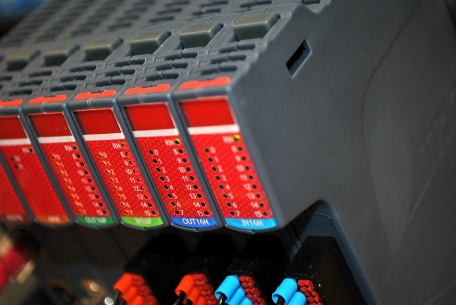
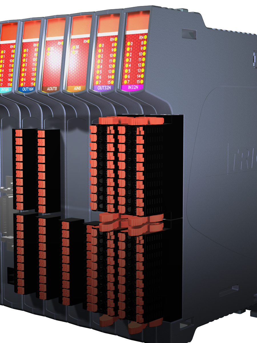
- Multiple practical push-in connector options – No break outs required.
- Clip-together design with ‘quick release’ locks for mechanical integrity.
- User labelling facility
- Machine builder custom functionality options
Easy to Use
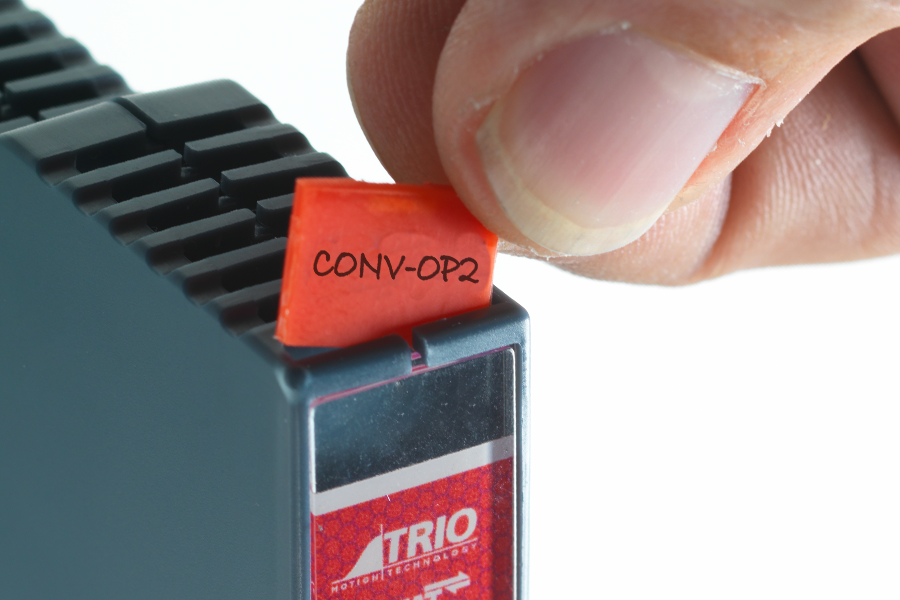
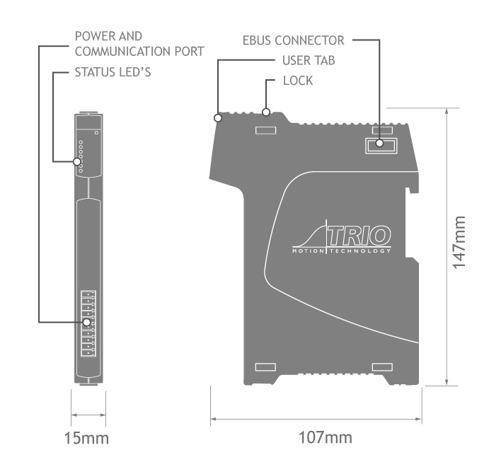
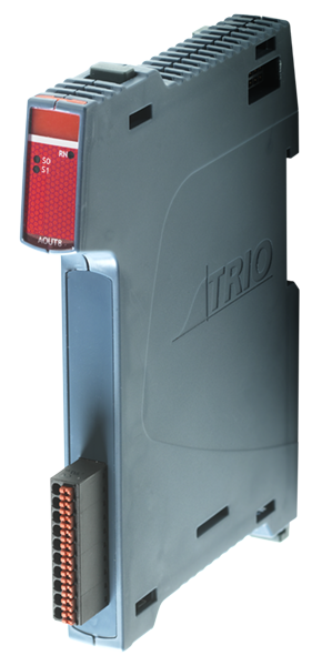
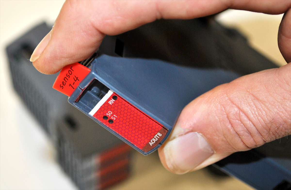
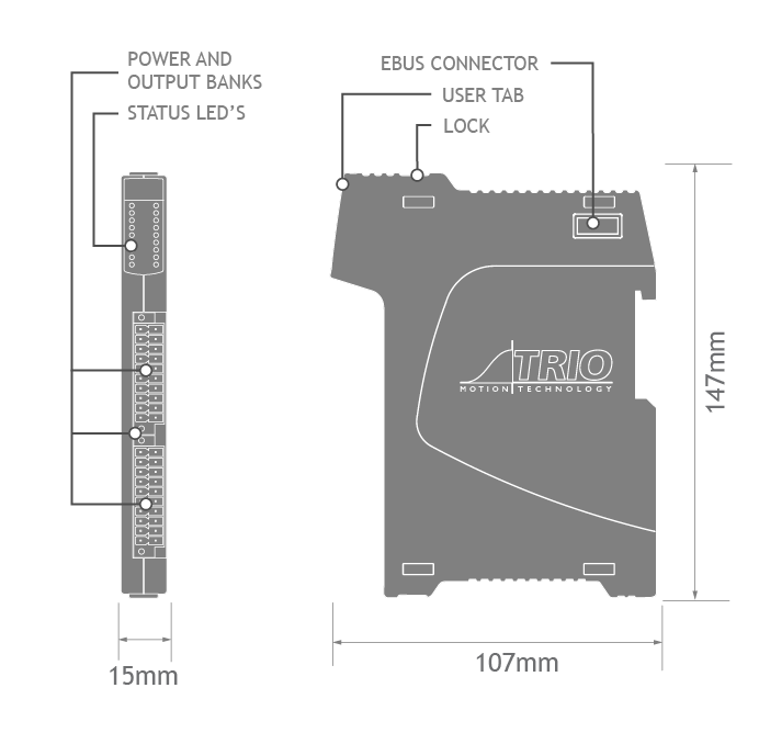
To help with identification of each Flexslice modules' function, a handy removable tab is provided that can be written on. It simply slides in and out of a slot at the top of each module.
Robust
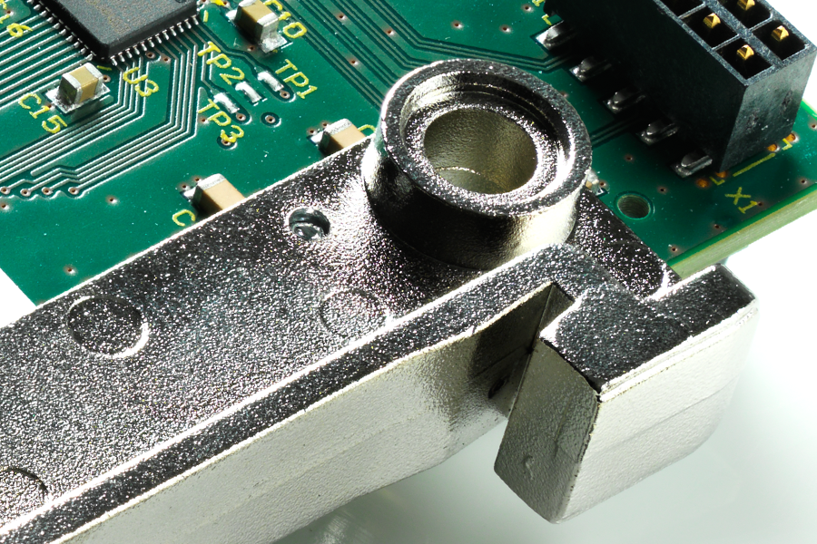
The robust metal chassis provides a good earth from the pcb of each module to the DIN rail to reduce noise and dissipate heat.
Practical
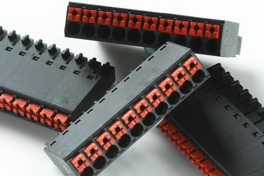
The easy to use push-in terminals makes wiring of the Flexslice system quick.
Customisation
The field programmable FPGA allows customisation of the functionality of some Flexslice Modules using Motion Perfect. The program can be "locked-down" creating a unique function for a machine builder which protects the functionality from being copied.
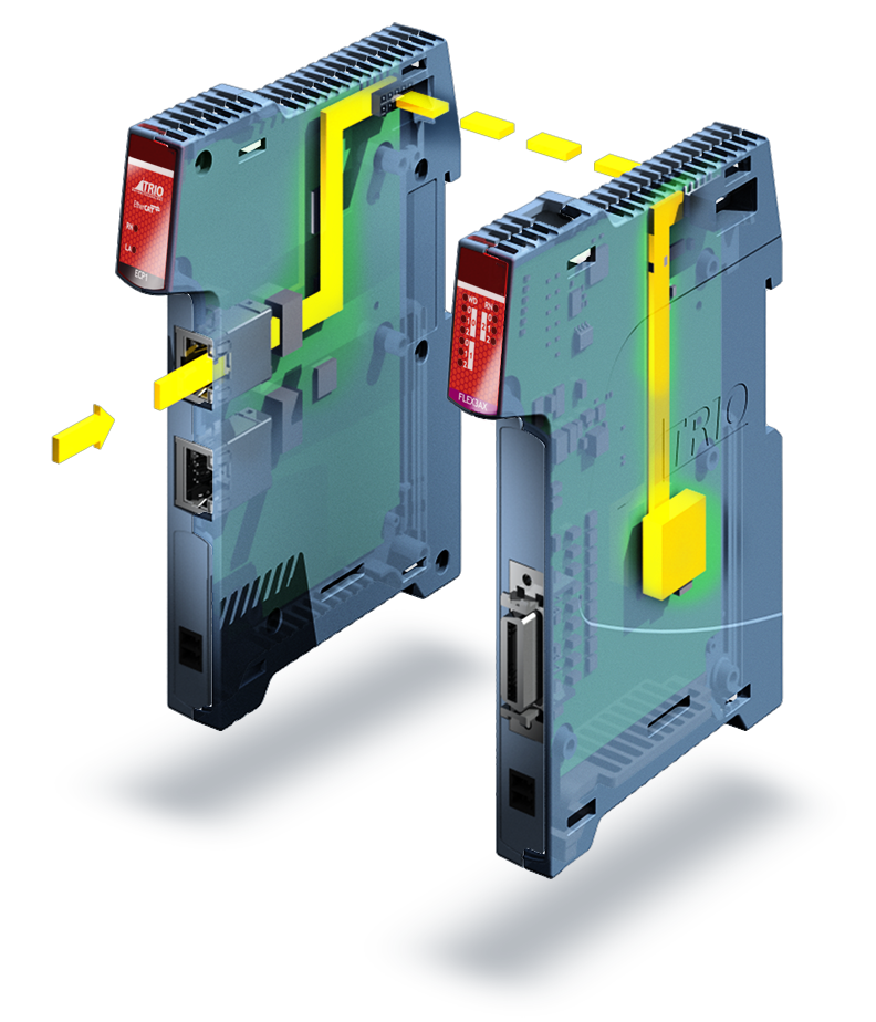
Build the System
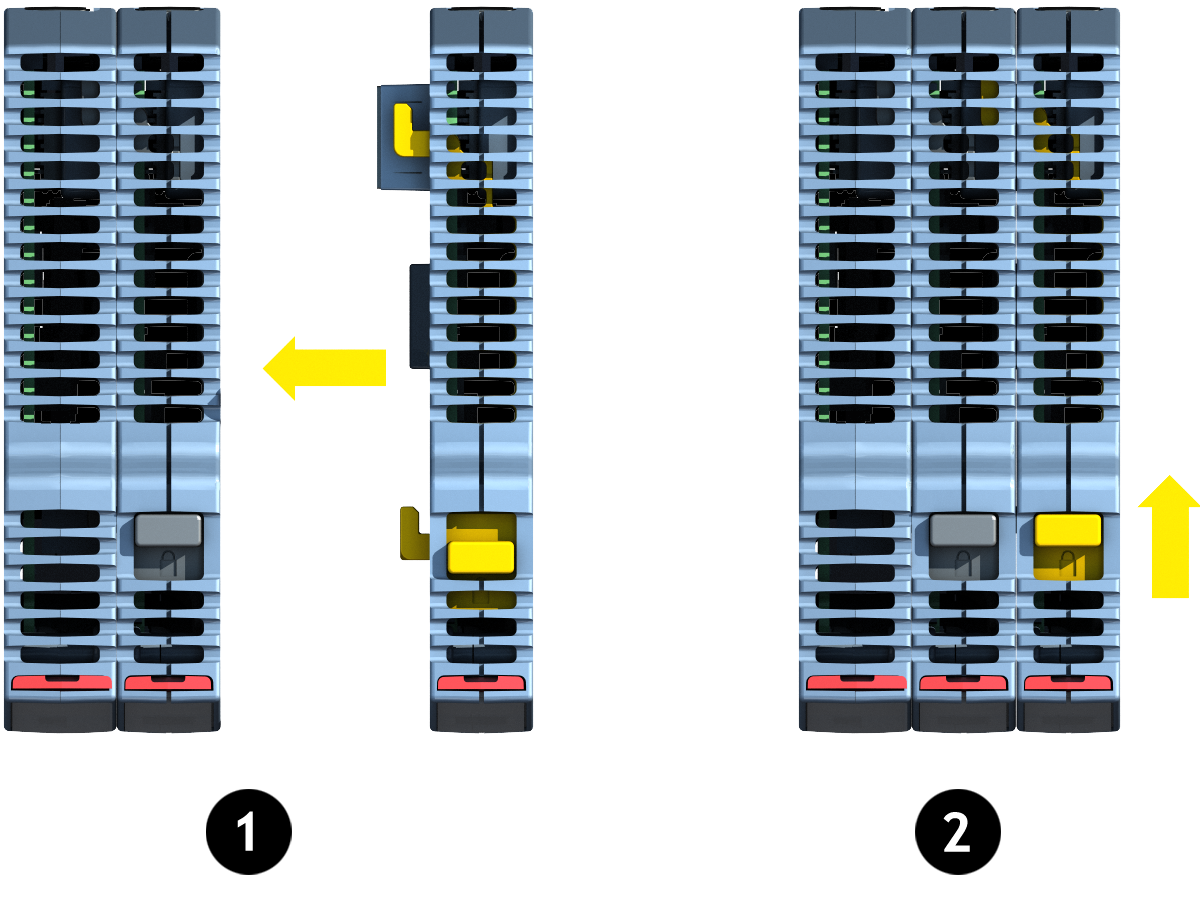
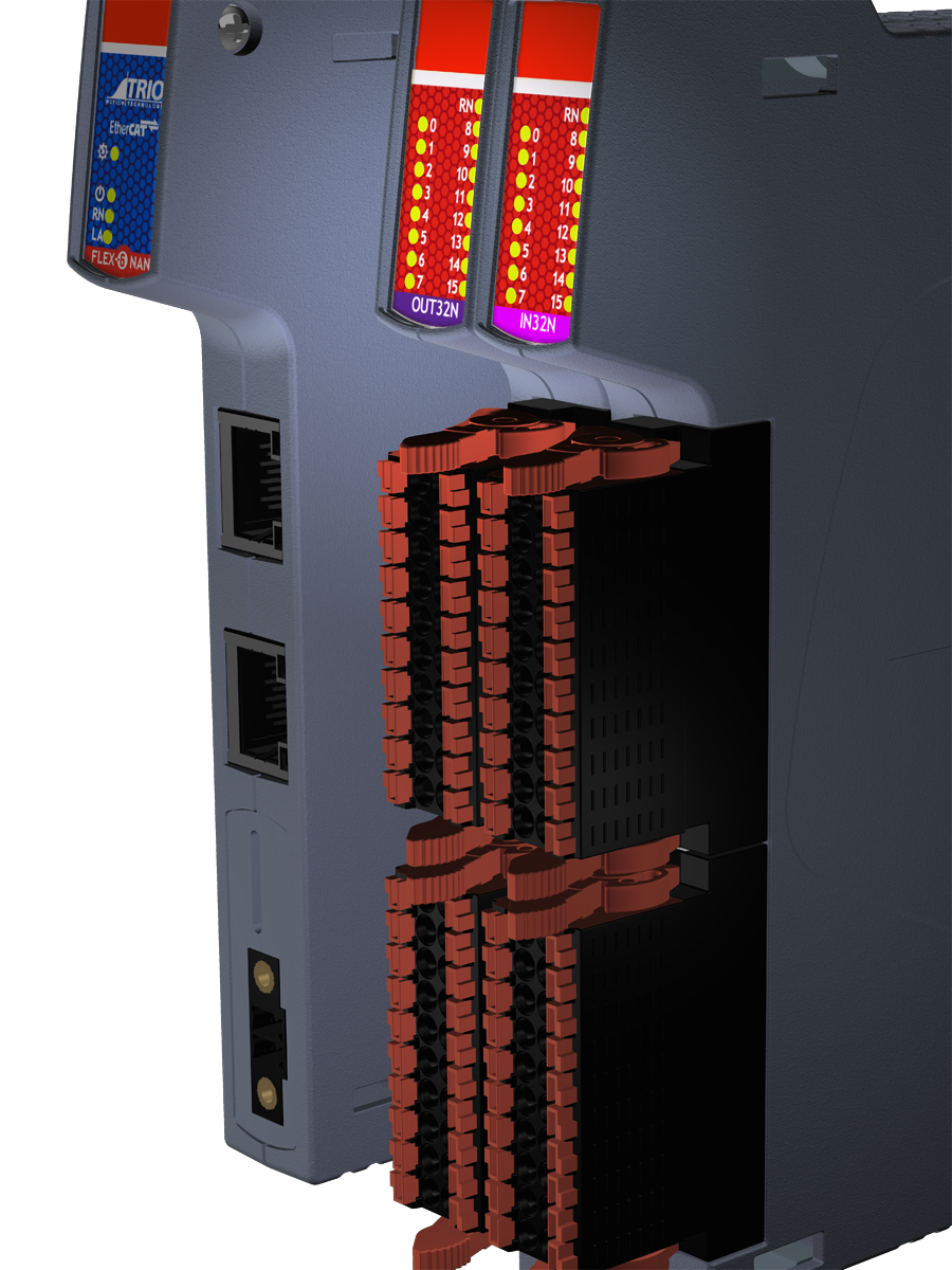
The positive "click-to-lock" mechanism firmly clamps Flexslice modules to each other to form a Flexslice station. Simply push each module together and slide the quick release locks into position.
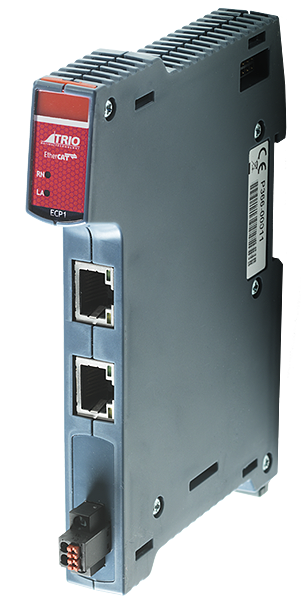
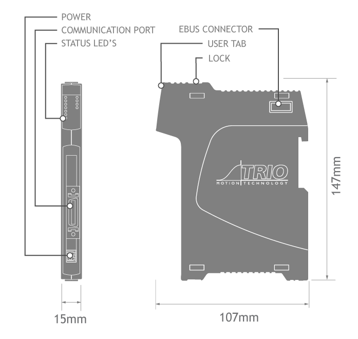
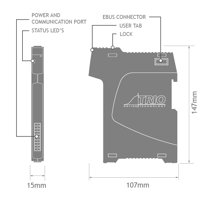
Coupler
P366
The Flexslice system begins with the coupler.
The coupler is connected to the network via the upper Ethernet interface. The lower RJ45 socket may be used to connect further EtherCAT devices in the same strand.
The bus coupler supports up to 16 input/output modules which have a positive mechanical lock and bus connector, making a reliable EBUS connection through the backplane. The complete assembly can be DIN rail mounted. The coupler converts the passing telegrams from Ethernet 100BASE-T to EBUS signal format.
In the EtherCAT network, the P366 coupler can be installed in any position in the Ethernet string; making it suitable for operation close to the master or at a remote position.
| Power supply requirement |
24V DC, 0.8A min for full system |
| EtherCAT Connection | RJ45 |
| Protocol | EtherCAT |
| Data rate | 100 Mbit/s |
| Power Supply | 24V / 1.5W |
| Isolation | 1KV |
| EtherCAT refresh cycle |
≥ 125us |
| Network Cable | CAT5e min |
| Mounting | DIN rail mount |
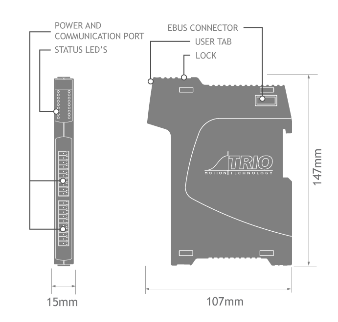
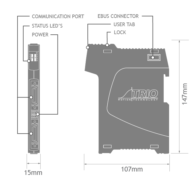
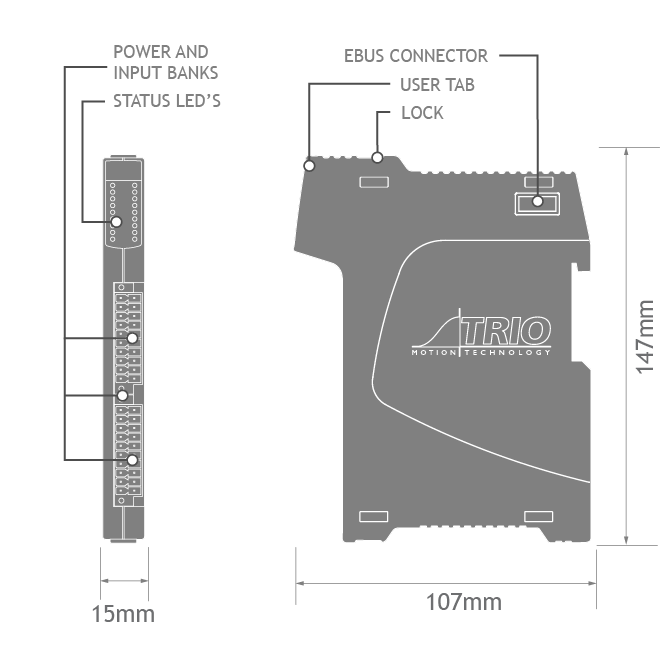
| Size (w x d x h) mm | 17.2 x 147 x 107 |
| Weight | 160g |
| Connectors | Push-in wiring terminals |
| EMC | EN61000-6-2 (2005) Industrial Noise Immunity/ EN61000-6-4 (2007) Industrial Noise Emissions. |
| RoHs, CE, UL | Compliant |
| Guides | |
|---|---|
| Data Sheet | |
| Quick Start Guide | Simple set up guide |
| EMC Guide | Electromagnetic Compatibility guide for Trio products v6 |
| Load calculator for Flexslice products | Excel table to calculate Slice Loading for P366-Coupler |
| Certificates | |
|---|---|
| EU Declaration | |
| UL Listing | Please insert E238097 UL File Number in the search box. |
| Manuals | |
|---|---|
| The Technical Reference Manual can be downloaded in full or as separate sections. All in PDF format. | |
| I-O Expansion Modules (Chapter 4).pdf | |
| CAD Data | |
|---|---|
| Drawings are available in various formats. These files are included in the Zip file below. | |
| CAD Model | |
| ESI Data | |
|---|---|
| Download zip file | EtherCAT Slave Configuration Information. |
| Customer Help | |
|---|---|
| Customer Support Forum | Trio has a world-wide technical support network providing information to our Distributors, Solution Partners and Customers. This page includes a knowledge-base, user forum and direct online ticketing system where answers will be provided by our engineers in the UK, USA, India, China and Italy. |
| Training Courses | Our 2-day introductory courses are designed to provide an overview of the Motion Coordinator product range and to give an introduction to programming using the Motion-iX technologies. The course is based upon practical worked examples of each topic covered to enable the attendees to gain some valuable hands-on experience of using Motion Perfect to develop applications. |
| Product Repair Information | We offer a fixed price repair service via our distributor network. This page provides information on how to get your product repaired. |
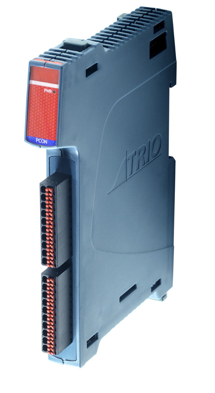
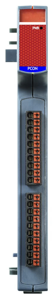
Power Connect Modules
P362
The P362 Flexslice Power Connect Module simplifies connection of three-wire sensors into the I/O system and removes the footprint and cost required for additional terminals. Easy wiring and multiple push-fit connections also make installation quicker and simpler.
The pins of the 2 x single-row push-in connectors (Power Connector 1 and Power Connector 2) are joined together to form 2 isolated banks of commoned connections. With 0V connected to the lower connector and 24V to the upper connector, the LED gives an indication that power is on.
| Module current consumption (EBUS 5V) | 0mA |
| Power supply requirement |
24V (+/-20%) dc |
| Max. Connector current |
4A |
| Mounting | DIN rail mount |
| Size (w x d x h) mm | 15 x 147 x 107 |
| Weight | 145g |
| Connectors | Push-in wiring terminals |
| EMC | EN61000-6-2 (2005) Industrial Noise Immunity/ EN61000-6-4 (2007) Industrial Noise Emissions. |
| RoHs, CE | Compliant |
| Guides | |
|---|---|
| Quick Start Guide | Simple set up guide |
| EMC Guide | Electromagnetic Compatibility guide for Trio products v6 |
| Certificates | |
|---|---|
| EU Declaration | |
| UL Listing | Please insert E238097 UL File Number in the search box. |
| CAD Data | |
|---|---|
| Drawings are available in the following formats: DXF, IGES, DWG and STEP. These files are included in the Zip file below. | |
| CAD Model | |
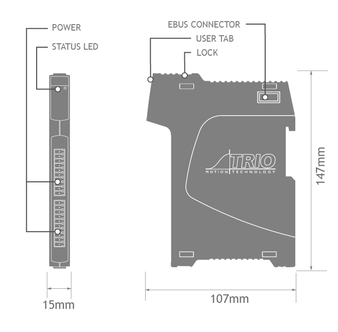
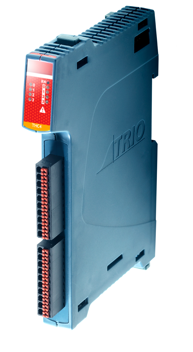
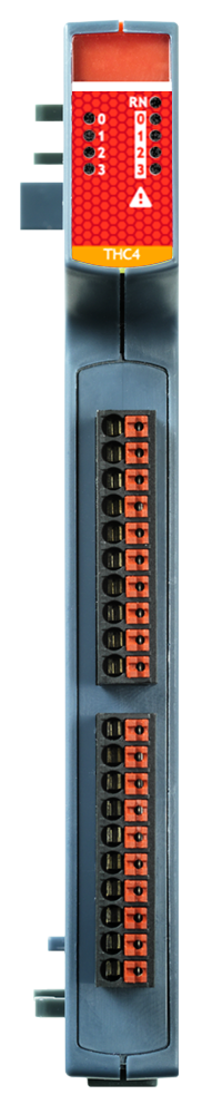
Thermocouple Module
P367
The P367 Flexslice Thermocouple module has 4 thermocouple inputs, each digitised to a resolution of 16 bit ensuring flexibility in meeting the needs of a range of applications for temperature measurement such as the monitoring of hot melt glue in sealing applications.
The P367 clicks-in to our P366 EtherCAT Flexslice I/O coupler as well as our pocket-sized 64 axis Flex-6 Nano Motion Coordinator. The slice joins a wide range of existing I/O that facilitates numerous digital and analogue integration options.
OEMs can deploy centralised as well as decentralised control of up to 128 axes with our motion-first machine solution. Our distributed I/O allows local connection to sensors and actuators while maintaining real-time performance over EtherCAT.
The 4 thermocouple inputs are brought out to a single row push-in connector. A second single row push-in connector has 4 relay outputs for control of a heater or other switched load.
| Module current consumption (EBUS 5V) | 160mA max |
| Power supply |
Via EBUS |
| Max. Output Voltage |
24V |
| Max. Output Current | 100mA |
| Number of Inputs | 4 |
| Thermocouple types | J, K, T, E |
| Resolution | 16 Bit |
| Number of Outputs | 4 |
| Output type | Normally open (NO) solid state relay |
| Load type | Resistive, inductive and capacitive |
| Mounting | DIN rail mount |
| Size (w x d x h) mm | 15 x 147 x 107 |
| Weight | 145g |
| Connectors | Push-in wiring terminals |
| EMC | EN61000-6-2 (2005) Industrial Noise Immunity/ EN61000-6-4 (2007) Industrial Noise Emissions. |
| RoHs, CE | Compliant |
| Guides | |
|---|---|
| Quick Start Guide | Simple set up guide |
| Application Note | Thermocouple User Guide |
| EMC Guide | Electromagnetic Compatibility guide for Trio products v6 |
| Certificates | |
|---|---|
| EU Declaration | |
| UL Listing | Please insert E238097 UL File Number in the search box. |
| Programming | |
|---|---|
| Example programms and firmware | |
| Demo Program for P367 | |
| Firmware P367 | |
| CAD Data | |
|---|---|
| Drawings are available in the following formats: DXF, IGES, DWG and STEP. These files are included in the Zip file below. | |
| CAD Model | |
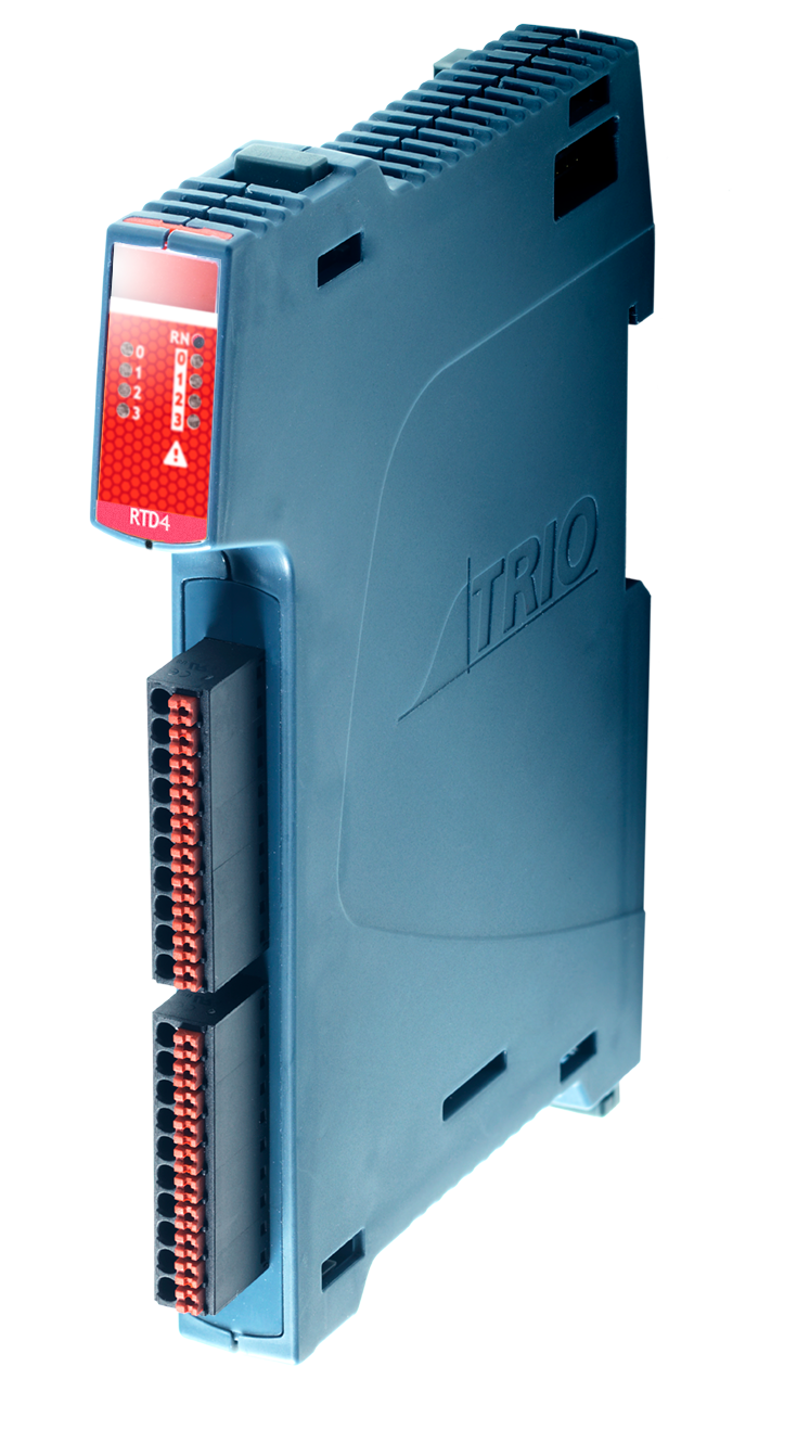
RTD Module
P368
The P368 Flexslice RTD module has 4 resistance temperature detector (RTD) inputs, each digitised to a resolution of 16 bit. The 4 RTD inputs are brought out to single row push-in connectors. 4 relay outputs are provided for control of a heater or other switched load.
The P368 clicks-in to our P366 EtherCAT Flexslice I/O coupler as well as our pocket-sized 64 axis Flex-6 Nano Motion Coordinator. The slice joins a wide range of existing I/O that facilitates numerous digital and analogue integration options.
OEMs can deploy centralised as well as decentralised control of up to 128 axes with our motion-first machine solution. Our distributed I/O allows local connection to sensors and actuators while maintaining real-time performance over EtherCAT.

| Module current consumption (EBUS 5V) | 160mA max |
| Power supply |
Via EBUS |
| Max. Output Voltage |
24V |
| Max. Output Current | 100mA |
| RTD types | PT100, PT1000 2 or 3 wire |
| Resolution | 16 Bit |
| Number of Intputs | 4 |
| Number of Outputs | 4 |
| Output type | Normally open (NO) solid state relay |
| Load type | Resistive, inductive and capacitive |
| Mounting | DIN rail mount |
| Size (w x d x h) mm | 15 x 147 x 107 |
| Weight | 145g |
| Connectors | Push-in wiring terminals |
| EMC | EN61000-6-2 (2005) Industrial Noise Immunity/ EN61000-6-4 (2007) Industrial Noise Emissions. |
| RoHs, CE | Compliant |
| Guides | |
|---|---|
| Quick Start Guide | Simple set up guide |
| EMC Guide | Electromagnetic Compatibility guide for Trio products v6 |
| Certificates | |
|---|---|
| EU Declaration | |
| UL Listing | Please insert E238097 UL File Number in the search box. |
| CAD Data | |
|---|---|
| Drawings are available in the following formats: DXF, IGES, DWG and STEP. These files are included in the Zip file below. | |
| CAD Model | |
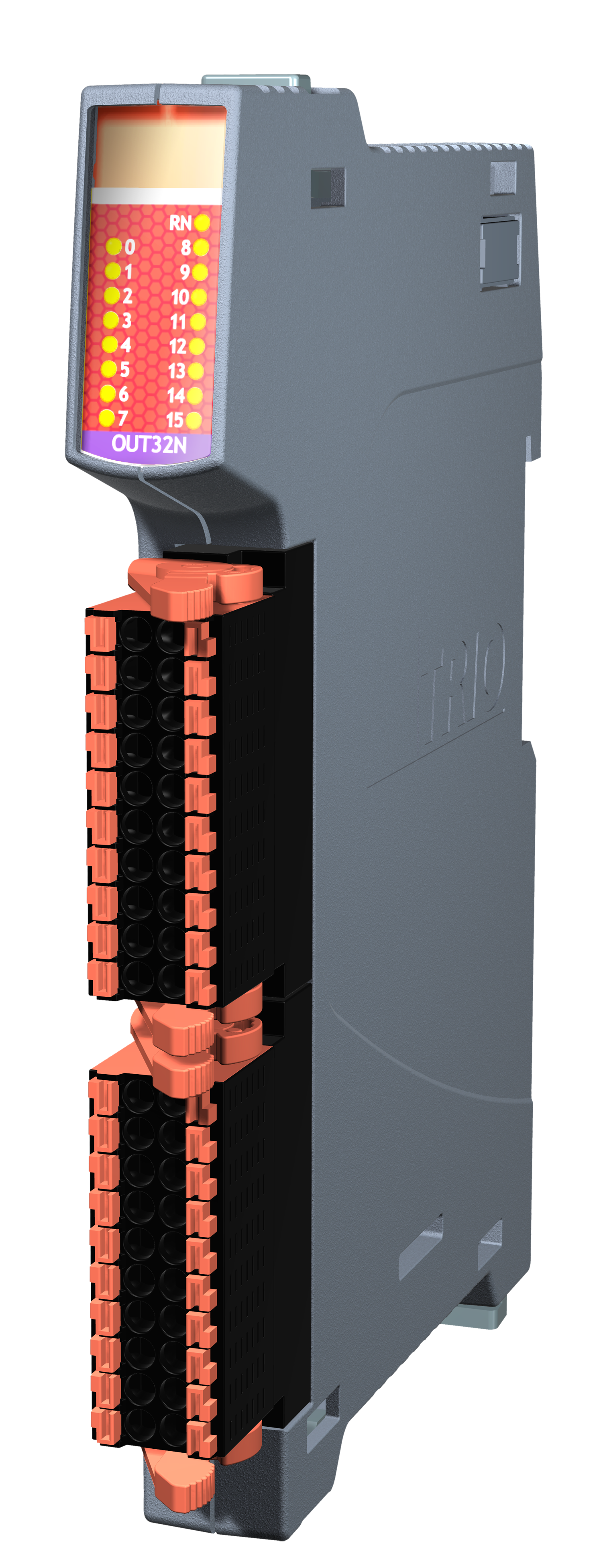
16-Out PNP
P371
This module is sold boxed in units of 10 as P471.
The P371 digital output slice connects the binary control signals from the Motion Coordinator to the machine’s output devices at 24V dc.
All 16 outputs are source (PNP) type and have electrical isolation. Outputs and power connection are via 2 x single-row plug-in screw terminal blocks. The Flexslice module indicates the output signal states via LEDs.

| Module current consumption (EBUS 5V) | 110mA max |
| Number of Digital Outputs |
16 (2 banks of 8) |
| Power supply requirement |
24V (+/-20%) DC |
| Load type |
Resistive, inductive and capacitive |
| "ON" time | 110us (10% to 90%) |
| "OFF" time |
210us (90% to 10%) |
| Max. Output current |
0.5A per channel 4A per bank of 8 Outputs |
| Short−Circuit Protection |
1.4A typ per output |
| Over voltage Protection |
Yes |
| Reverse Voltage Protection | Yes |
| Power Supply | 24V / 1.5W |
| Isolation | 1KV |
| Mounting | DIN rail mount |
| Size (w x d x h) mm | 15 x 147 x 107 |
| Weight | 145g |
| Op Temp Range | 0 to 45°C |
| Storage Temp Range | -25 to 70°C |
| Humidity Rating | <85% humidity (non-condensing) |
| Connectors | Push-in wiring terminals |
| EMC | EN61000-6-2 (2005) Industrial Noise Immunity/ EN61000-6-4 (2007) Industrial Noise Emissions. |
| RoHs, CE, UL | Compliant |
| Guides | |
|---|---|
| Data Sheet | |
| Quick Start Guide | Simple set up guide |
| EMC Guide | Electromagnetic Compatibility guide for Trio products v6 |
| Certificates | |
|---|---|
| EU Declaration | |
| UL Listing | Please insert E238097 UL File Number in the search box. |
| Manuals | |
|---|---|
| The Technical Reference Manual can be downloaded in full or as separate sections. All in PDF format. | |
| I-O Expansion Modules (Chapter 4).pdf | |
| CAD Data | |
|---|---|
| Drawings are available in the following formats: DXF, IGES, DWG and STEP. These files are included in the Zip file below. | |
| CAD Model | |
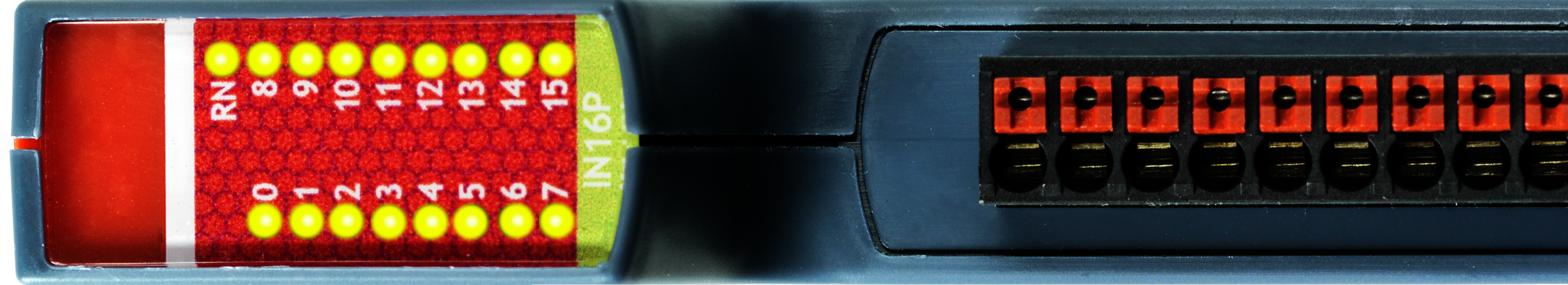
16-in PNP
P372
This module is sold boxed in units of 10 as P472.
The P372 digital input slice connects 24V dc signals from devices on the machine to the binary control registers in the Motion Coordinator.
All 16 inputs are source (PNP) type and have electrical isolation. Inputs and power connection are via 2 x single-row plug-in screw terminal blocks. The Flexslice module indicates the input signal states via LEDs.
| Module current consumption (EBUS 5V) | 110mA max |
| Number of Digital Outputs |
16 (2 banks of 8) |
| Power supply requirement |
24V (+/-20%) DC |
| Load type |
Resistive, inductive and capacitive |
| "ON" Voltage | 11.2V typ |
| "OFF" Voltage |
10.2V typ |
| Input current |
3.5mA typ |
| Input filter Cut-off (RC network) |
18KHz |
| Mounting | DIN rail mount |
| Size (w x d x h) mm | 15 x 147 x 107 |
| Weight | 145g |
| Operating Temp Range | 0 to 45°C |
| Storage Temp Range | -25 to 70°C |
| Humidity Rating | <85% humidity (non-condensing) |
| Connectors | Push-in wiring terminals |
| EMC | EN61000-6-2 (2005) Industrial Noise Immunity/ EN61000-6-4 (2007) Industrial Noise Emissions. |
| RoHs, CE, UL | Compliant |

| Guides | |
|---|---|
| Data Sheet | |
| Quick Start Guide | Simple set up guide |
| EMC Guide | Electromagnetic Compatibility guide for Trio products v6 |
| Certificates | |
|---|---|
| EU Declaration | |
| UL Listing | Please insert E238097 UL File Number in the search box. |
| Manuals | |
|---|---|
| The Technical Reference Manual can be downloaded in full or as separate sections. All in PDF format. | |
| I-O Expansion Modules (Chapter 4).pdf | |
| CAD Data | |
|---|---|
| Drawings are available in the following formats: DXF, IGES, DWG and STEP. These files are included in the Zip file below. | |
| CAD Model | |
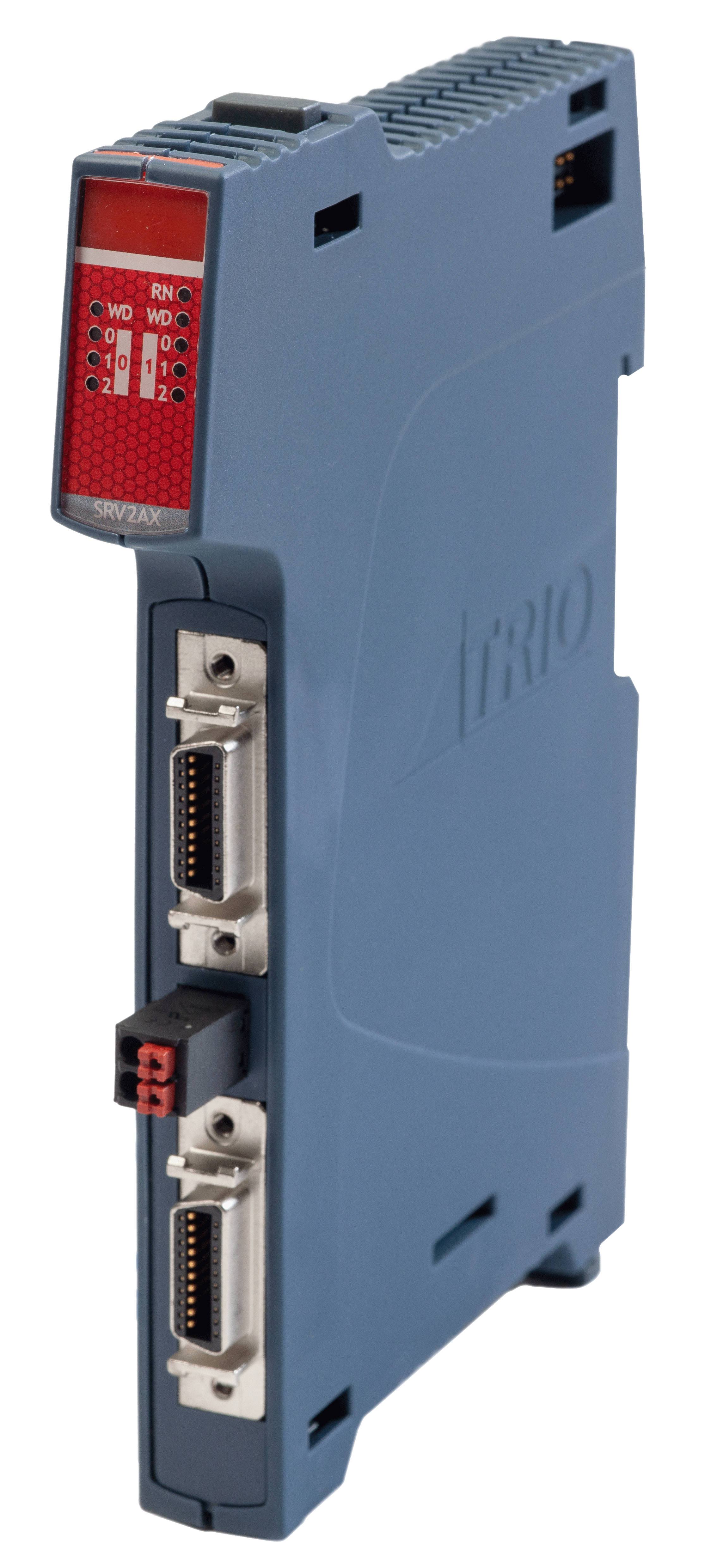
Analogue 2 Servo Axes
P374
The P374 2 Axis Servo slice will click-in to our EtherCAT Flexslice I/O range as well compatible Motion Coordinator. The slice will enable integration of non-EtherCAT servo drives, stepper drives and encoders.
An advantage of the I/O slice approach compared to a traditional PLC for analogue and stepper integration is a saving on footprint and cost, combined with our motion-first specialisation.
It supports incremental encoder inputs. A stepper / pulse output axis can be configured to be pulse+direction output. Two 20 way MDR connectors (Axis 0 and 1) provide a reliable shielded connection for high speed signals. Each MDR connector supports all the signals for full closed loop control of a servo axis.
| Module current consumption (EBUS 5V) | 180mA max |
| Max Axes |
2 (software configurable) |
| Power supply requirement |
24V (+/-20%) dc Class 2 transformer or power supply @ 100mA |
| Max Enc Rate |
8M Edges/s encoder count |
| Max Step Rate | 2MHz pulse count |
| Step / Pulse Width |
Pulse Control or Square Wave |
| Enc / Step Input / Output |
RS422 |
| DAC Voltage Output |
2 x 12bit +/-10V @ 5mA |
| WDOG Output | 2 x Normally open (NO) solid state relay |
| WDOG Max. Output Voltage | 24V |
| WDOG Max Output Current | 100mA |
| Field Programmable | Yes |
| Mounting | DIN rail mount |
| Size (w x d x h) mm | 15 x 147 x 107 |
| Weight | 145g |
| Connectors | Push-in wiring terminals |
| EMC | EN61000-6-2 (2005) Industrial Noise Immunity/ EN61000-6-4 (2007) Industrial Noise Emissions. |
| RoHs, CE | Compliant |
| Guides | |
|---|---|
| Quick Start Guide | Simple set up guide |
| EMC Guide | Electromagnetic Compatibility guide for Trio products v6 |
| Manual | |
|---|---|
| Full Manual | The Technical Reference Manual can be downloaded in PDF format. |
| Certificates | |
|---|---|
| EU Declaration of Conformity | EU Declaration of Conformity Certificate |
| Country of Origin | Country of Origin Certificate |
| Firmware - P374 | ||||||
|---|---|---|---|---|---|---|
|
Latest USER Release:
|
| CAD Data | |
|---|---|
| Drawings are available in the following formats: DXF, IGES, DWG and STEP. These files are included in the Zip file below. | |
| CAD Model | |
| Products - Generic |
|---|
3m MDR cable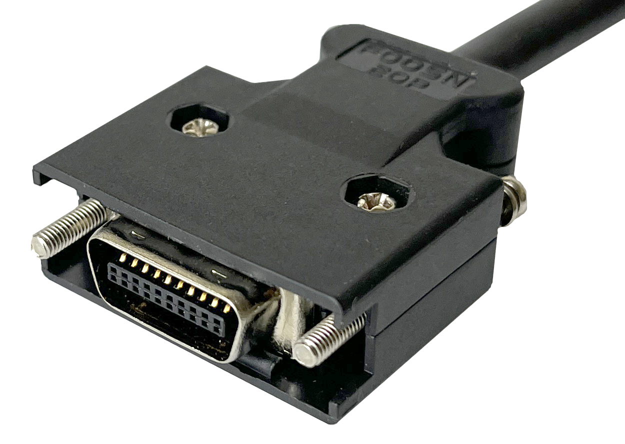 Additional 3 metre 20 way MDR connector. The P392 has one end finishing as a flying lead. |
3 Axis Step Pulse
P375
The P375 Flexslice 3 Axis Step Pulse Module controls up to 3 Stepper motors with Pulse/Direction/Enable or Pulse/Direction/Registration signals for each axis.
It supports incremental encoders. If configured for stepper / pulse output an axis can be pulse+direction or quadrature simulated encoder output. A single MDR connector provides a reliable shielded 26 way connector for high speed signals. The P375 is compatible with most high resolution microstep drives.

| Module current consumption (EBUS 5V) | 150mA max | Module current consumption (24V) | 90mA max |
| Max Step Rate |
8MHz pulse count |
| Step / Pulse Width |
Pulse Control or Square Wave |
| Max Enc Rate |
8MHz encoder count |
| Step/Enc Port | MDR Connector 0...5V |
Encoder Power Output (5V) | 150mA max (Shared Between 3 Axes) |
| Max Axes |
3 (software configurable) |
| WDOG Output |
Yes |
| Field Programmable |
Yes |
| Mounting | DIN rail mount |
| Size (w x d x h) mm | 15 x 147 x 107 |
| Weight | 145g |
| Connectors | Push-in wiring terminals |
| EMC | EN61000-6-2 (2005) Industrial Noise Immunity/ EN61000-6-4 (2007) Industrial Noise Emissions. |
| RoHs, CE, UL | Compliant |
| Guides | |
|---|---|
| Quick Start Guide | Simple set up guide | EMC Guide | Electromagnetic Compatibility guide for Trio products v6 |
| Certificates | |
|---|---|
| EU Declaration | |
| UL Listing | Please insert E238097 UL File Number in the search box. |
| Manuals | |
|---|---|
| The Technical Reference Manual can be downloaded in full or as separate sections. All in PDF format. | |
| I-O Expansion Modules (Chapter 4).pdf | |
| Application Notes |
|---|
| AN-380-Describes configuration of P375 for operation with a Trio controller |
| Firmware - P375 | ||||||
|---|---|---|---|---|---|---|
|
Latest USER Release:
|
| CAD Data | |
|---|---|
| Drawings are available in the following formats: DXF, IGES, DWG and STEP. These files are included in the Zip file below. | |
| CAD Model | |
| Products - Generic |
|---|
3m MDR cable Additional 3 metre 26 way MDR connector. The P384 has one end finishing as a flying lead. |
16-Out NPN
P376
This module is sold boxed in units of 10 as P476.
The P376 digital output slice connects the binary control signals from the Motion Coordinator to the machine’s output devices, such as relays, contactors, valves, lamps etc. at 24V dc.
All 16 outputs are sink (NPN) type and have electrical isolation. Outputs and power connection are via 2 x single-row plug-in screw terminal blocks. The Flexslice module indicates the output signal states via LEDs.

| Module current consumption (EBUS 5V) | 110mA max |
| Number of Digital Outputs |
16 (2 banks of 8) |
| Power supply requirement |
24V (+/-20%) DC |
| Load type |
Resistive, inductive and capacitive |
| "ON" time | 75us (90% to 10%) |
| "OFF" time |
105us (10% to 90%) |
| Max output current |
0.5A per channel 4A per bank of 8 Outputs |
| Short−Circuit Protection |
3A typ per output |
| Over / Reverse voltage Protection |
Yes |
| Mounting | DIN rail mount |
| Size (w x d x h) mm | 15 x 147 x 107 |
| Weight | 145g |
| Connectors | Push-in wiring terminals |
| EMC | EN61000-6-2 (2005) Industrial Noise Immunity/ EN61000-6-4 (2007) Industrial Noise Emissions. |
| RoHs, CE, UL | Compliant |

| Guides | |
|---|---|
| Data Sheet | |
| Quick Start Guide | Simple set up guide |
| EMC Guide | Electromagnetic Compatibility guide for Trio products v6 |
| Certificates | |
|---|---|
| EU Declaration | |
| UL Listing | Please insert E238097 UL File Number in the search box. |
| Manuals | |
|---|---|
| The Technical Reference Manual can be downloaded in full or as separate sections. All in PDF format. | |
| I-O Expansion Modules (Chapter 4).pdf | |
| CAD Data | |
|---|---|
| Drawings are available in the following formats: DXF, IGES, DWG and STEP. These files are included in the Zip file below. | |
| CAD Model | |
16-In NPN
P377
This module is sold boxed in units of 10 as P477.
The P377 digital input Flexslice connects 24V dc signals from devices on the machine to the binary control registers in the Motion Coordinator.
All 16 inputs are current sourcing (NPN) type and have electrical isolation. Inputs and power connection are via 2 x single-row push-in connectorss. The Flexslice module indicates the input signal states via LEDs
| Module current consumption (EBUS 5V) | 100mA max |
| Number of Digital Inputs |
16 (2 banks of 8) |
| Power supply requirement |
24V (+/-20%) DC |
| Load type |
Resistive, inductive and capacitive |
| "ON" Voltage | 13.7V typ |
| "OFF" Voltage |
14.6V typ |
| Input current |
3.5mA typ |
| Input filter Cut-off (RC network) |
18KHz |
| Mounting | DIN rail mount |
| Size (w x d x h) mm | 15 x 147 x 107 |
| Weight | 145g |
| Connectors | Push-in wiring terminals |
| EMC | EN61000-6-2 (2005) Industrial Noise Immunity/ EN61000-6-4 (2007) Industrial Noise Emissions. |
| RoHs, CE, UL | Compliant |
| Guides | |
|---|---|
| Data Sheet | |
| Quick Start Guide | Simple set up guide |
| EMC Guide | Electromagnetic Compatibility guide for Trio products v6 |
| Certificates | |
|---|---|
| EU Declaration | |
| UL Listing | Please insert E238097 UL File Number in the search box. |
| Manuals | |
|---|---|
| The Technical Reference Manual can be downloaded in full or as separate sections. All in PDF format. | |
| I-O Expansion Modules (Chapter 4).pdf | |
| CAD Data | |
|---|---|
| Drawings are available in the following formats: DXF, IGES, DWG and STEP. These files are included in the Zip file below. | |
| CAD Model | |
8 Analogue Outputs
P378
This module is sold boxed in units of 10 as P459.
The P378 Flexslice 8 Analogue Output module has eight programmable voltage range output terminals, each digitised to a resolution of 12 bit.
The 8 single ended outputs have a common 0V potential and are brought out to a single push-in connector.
| Module current consumption (EBUS 5V) | 200mA max |
| Number of Analogue Outputs |
8 |
| Power supply requirement |
via the EBUS |
| Signal Voltage | -10V ... +10V : 0V ... +10V |
| Signal current |
+/-5mA max |
| Resolution | 12 bit |
| Output impedance |
16 Ohm |
| Mounting | DIN rail mount |
| Size (w x d x h) mm | 15 x 147 x 107 |
| Weight | 145g |
| Connectors | Push-in wiring terminals |
| EMC | EN61000-6-2 (2005) Industrial Noise Immunity/ EN61000-6-4 (2007) Industrial Noise Emissions. |
| RoHs, CE, UL | Compliant |
| Guides | |
|---|---|
| Data Sheet | |
| Quick Start Guide | Simple set up guide |
| EMC Guide | Electromagnetic Compatibility guide for Trio products v6 |
| Certificates | |
|---|---|
| EU Declaration | |
| UL Listing | Please insert E238097 UL File Number in the search box. |
| Manuals | |
|---|---|
| The Technical Reference Manual can be downloaded in full or as separate sections. All in PDF format. | |
| I-O Expansion Modules (Chapter 4).pdf | |
| CAD Data | |
|---|---|
| Drawings are available in the following formats: DXF, IGES, DWG and STEP. These files are included in the Zip file below. | |
| CAD Model | |
8 Analogue Inputs
P379
The P379 Flexslice 8 Analogue Input module has eight programmable voltage range input terminals, each digitised to a resolution of 12 bit.
The 8 single ended inputs have a common 0V potential and are brought out to a single row plug-in screw terminal block. The signal state is indicated by 8 LEDs with variable light intensity.
| Module current consumption (EBUS 5V) | 160mA max |
| Number of Analogue Inputs |
8 |
| Power supply requirement |
via the EBUS |
| Signal Voltage |
-5 …+5V; 0 …+5V; -10 …+10V; 0 …+10V |
| Resolution | 12 bit |
| Overvoltage protection |
±25V |
| Mounting | DIN rail mount |
| Size (w x d x h) mm | 15 x 147 x 107 |
| Weight | 145g |
| Connectors | Push-in wiring terminals |
| EMC | EN61000-6-2 (2005) Industrial Noise Immunity/ EN61000-6-4 (2007) Industrial Noise Emissions. |
| RoHs, CE, UL | Compliant |

| Guides | |
|---|---|
| Data Sheet | |
| Quick Start Guide | Simple set up guide |
| EMC Guide | Electromagnetic Compatibility guide for Trio products v6 |
| Certificates | |
|---|---|
| EU Declaration | |
| UL Listing | Please insert E238097 UL File Number in the search box. |
| Manuals | |
|---|---|
| The Technical Reference Manual can be downloaded in full or as separate sections. All in PDF format. | |
| I-O Expansion Modules (Chapter 4).pdf | |
| CAD Data | |
|---|---|
| Drawings are available in the following formats: DXF, IGES, DWG and STEP. These files are included in the Zip file below. | |
| CAD Model | |
New
2026
8-In Analogue Current
P359
This module is sold boxed in units of 10 as P459.
The P359 Flexslice 8-In Analogue Current Input module has eight input terminals, each digitised to a resolution of 12 bit.
The 8 single ended inputs have a common 0V potential and are brought out to a single row push-in connector.
| Module current consumption (EBUS 5V) | 160mA max |
| Number of Analogue Inputs | 8 |
| Input ranges | 4-20mA |
| Input Accuracy | 100uA |
| Max Input Frequency | 100kHz |
| Overvoltage protection | ±25V |
| Isolation | 3.75kV |
| Power supply requirement | Via the EBUS |
| Resolution | 12 bit |
| Mounting | DIN rail mount |
| Size (w x d x h) mm | 15 x 147 x 107 |
| Weight | 145g |
| Connectors | Push-in wiring terminals |
| EMC | BS EN 61000-6-4:2019 Electromagnetic Compatibility/ BS EN 61000-6-2:2019 Electromagnetic Compatibility |
| Operating temperature | 0 - 45°C |
| RoHs, CE | Compliant |
| Guides | |
|---|---|
| Quick Start Guide | Simple set up guide |
| EMC Guide | Electromagnetic Compatibility guide for Trio products v6 |
| Manuals | |
|---|---|
| The Technical Reference Manual can be downloaded in PDF format. | |
| Technical Reference Manual | |
| Certificates | |
|---|---|
| P359 - EU Declaration | |
| P359 - UK Declaration | |
| UL Listing | Please insert E238097 UL File Number in the search box. |
| CAD Data | |
|---|---|
| Drawings are available in the following formats: DXF, IGES, DWG and STEP. These files are included in the Zip file below. | |
| CAD Model | |
32-Out NPN
P386
This module is sold boxed in units of 10 as P483.
The P386 digital output slice connects the binary control signals from the Motion Coordinator to the machine’s input devices, such as relays, contactors, valves, lamps etc. at 24V dc.
The 32 I/O modules are a cost-effective distributed I/O solution for your application that requires maximum efficiency and performance in a small space. In addition to the compact size, our reliable EBUS connection through the backplane reduces the need for any additional hardware and wiring even further.
All 32 inputs are current sinking (NPN) type and have electrical isolation. Inputs and power connection are via 2 x double-row push-in connectors. The Flexslice module indicates the input signal states via LEDs.
| Module current consumption (EBUS 5V) | 160mA max |
| Output-Bank 1 | 16 x NPN Output, 3.5mA typ, 24V dc common |
| Output-Bank 2 | 16 x NPN Output, 3.5mA typ, 24V dc common |
| Power supply requirement | 24V (+/-20%) DC |
| Load type | Resistive, inductive and capacitive |
| "ON" Voltage | 13.7V typ |
| "OFF" Voltage | 14.6V typ |
| Input current |
3.5mA typ |
| Input filter Cut-off (RC network) |
18KHz |
| Mounting | DIN rail mount |
| Size (w x d x h) mm | 15 x 147 x 107 |
| Weight | 145g |
| Connectors | Push-in wiring terminals |
| EMC | EN61000-6-2 (2005) Industrial Noise Immunity/ EN61000-6-4 (2007) Industrial Noise Emissions. |
| RoHs, CE | Compliant |
| Guides | |
|---|---|
| Data Sheet | |
| Quick Start Guide | Simple set up guide |
| EMC Guide | Electromagnetic Compatibility guide for Trio products v6 |
| Certificates | |
|---|---|
| EU Declaration | |
| UL Listing | Please insert E238097 UL File Number in the search box. |
| CAD Data | |
|---|---|
| Drawings are available in the following formats: DXF, IGES, DWG and STEP. These files are included in the Zip file below. | |
| CAD Model | |
32-In NPN
P387
This module is sold boxed in units of 10 as P484.
The P387 digital input slice connects 24V dc signals from devices on the machine to the binary control registers in the Motion Coordinator.
The 32 I/O modules are a cost-effective distributed I/O solution for your application that requires maximum efficiency and performance in a small space. In addition to the compact size, our reliable EBUS connection through the backplane reduces the need for any additional hardware and wiring even further.
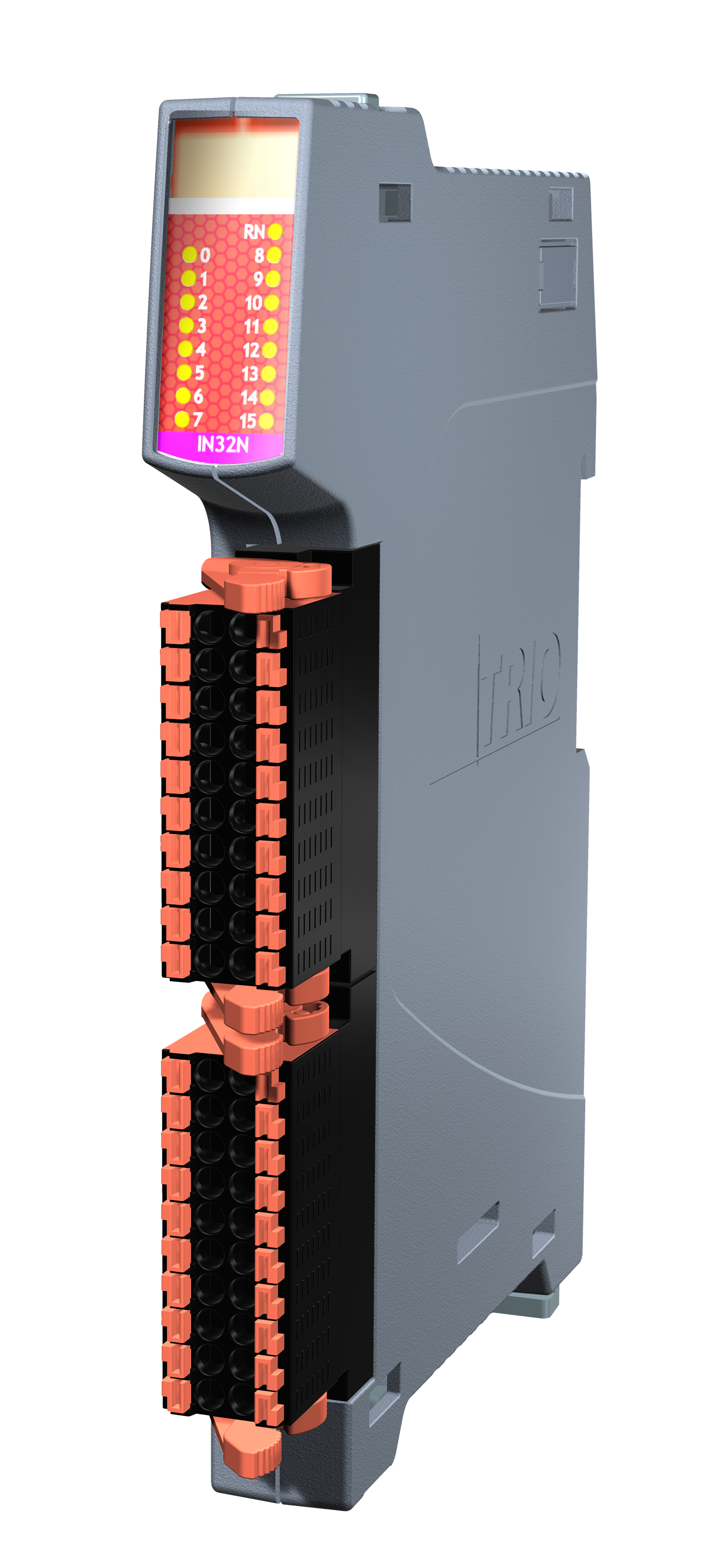
All 32 inputs are current sourcing (NPN) type and have electrical isolation. Inputs and power connection are via 2 x double-row push-in connectors. The Flexslice module indicates the input signal states via LEDs.
| Module current consumption (EBUS 5V) | 160mA max |
| Input-Bank 1 | 16 x NPN Inputs, 3.5mA typ, 24V dc common |
| Input-Bank 2 | 16 x NPN Inputs, 3.5mA typ, 24V dc common |
| Power supply requirement |
24V (+/-20%) DC |
| Load type |
Resistive, inductive and capacitive |
| "ON" Voltage | 13.7V typ |
| "OFF" Voltage |
14.6V typ |
| Input current |
3.5mA typ |
| Input filter Cut-off (RC network) |
18KHz |
| Mounting | DIN rail mount |
| Size (w x d x h) mm | 15 x 147 x 107 |
| Weight | 145g |
| Connectors | Push-in wiring terminals |
| EMC | EN61000-6-2 (2005) Industrial Noise Immunity/ EN61000-6-4 (2007) Industrial Noise Emissions. |
| RoHs, CE | Compliant |
| Guides | |
|---|---|
| Data Sheet | |
| Quick Start Guide | Simple set up guide |
| EMC Guide | Electromagnetic Compatibility guide for Trio products v6 |
| Certificates | |
|---|---|
| EU Declaration | |
| UL Listing | Please insert E238097 UL File Number in the search box. |
| CAD Data | |
|---|---|
| Drawings are available in the following formats: DXF, IGES, DWG and STEP. These files are included in the Zip file below. | |
| CAD Model | |
